Morph
A circuit prototyping assistant that helps build , design, and debug your circuit. With camera vision and automatic wire stripping capabilities, Morph bridges the gap between abstract circuit diagram and functional prototype, making circuit design a fun and intuitive process for beginners and hobbyists. It is an ongoing project.
Info:
Personal Project
2024 Spring, 9 weeks
MIT Tool Design
Teammate
Selin Dursun (Software Integration, Design)
Create work-like prototype
Conduct User / Market Research
Interface Design
Skills:
Industrial Design; Physical Prototyping; UI/UX
Tools:
Solidworks; Figma; 3D Printing; Model Making
Role:
Circuit prototyping is repetitive and time consuming.
Between ideating, designing, building, and debugging, physical wiring is what connects abstract diagrams with functional prototypes. It is also the most repetitive stage of the process and where errors are prone to happen
User Research
User Journey Map
User Persona
Market Analysis
Research Insights
How do we bridge the gap between digital circuit design and physical prototyping to create a more intuitive design experience?
Brainstorming
Machine Architecture
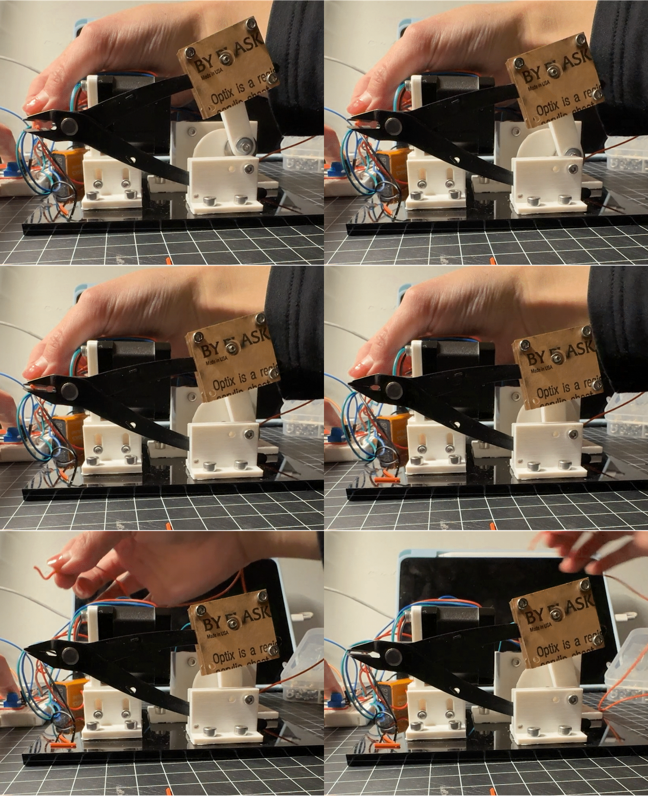
Below is a side view of the machine architecture, operated in the order of
feeding -> stripping -> cutting -> bending
Below is a side view of the machine architecture, operated in the order of
feeding -> stripping -> cutting -> bending
Subsystem Prototype
Cutter / Stripper
Cutter / Stripper Design 2
Wire Spool Changer / Feeder
Most Recent Work Like Prototype
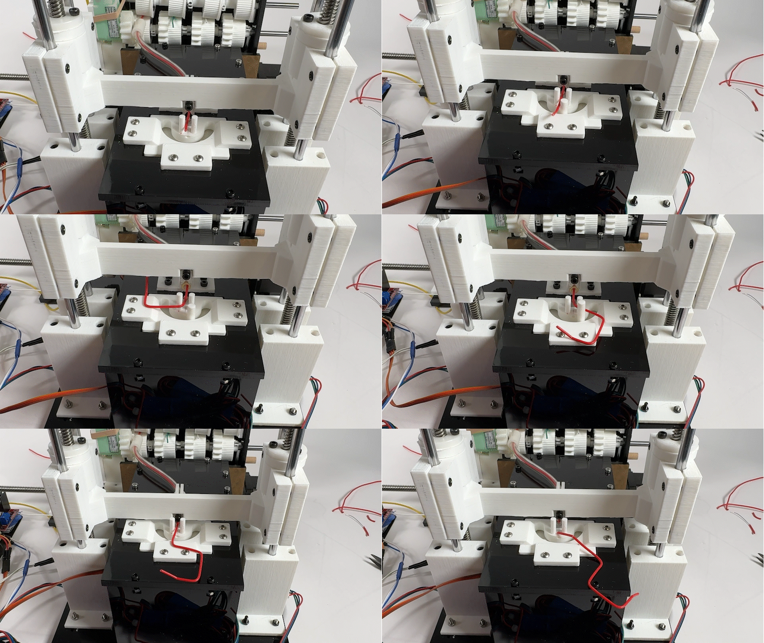
This integrated model combines the feeding, stripping and bending mechanisms, able to translate simple wire drawings into machine actions.
Updated User Interaction
With integrated camera vision and automated wire stripping/bending, users can much more directly and intuitively design, plan, prototype, and debug their circuits without manually transferring the design from paper to breadboard to simulator and product more more reliable and faster wire connections.
Camera Vision
We explored hole detection on breadboard with the goal of translating breadboard to digital interfaces, capturing both holes and the components on the board.
Work With Morph
Morph works alongside physical circuits to help
Capture breadboard assembly,
Plan out circuit layout
Strip/Bend corresponding wires.
Order Of Operation
2. Draw Desired Route
3. Select Route & Send To Machine
4. Place Wire On Breadbaord
Place Breadboard
Machine Interface
The MVP of the concept involves a simple wire connecting interface. The camera captures the breadboard and components, converting them into a dot interface that can be easily routed by clicking turning points.
Draw Desired Wire Route
Multi-Spool Management
Component Library
Morph is paired with an extensive component library, allowing users to visualize the circuit layout directly over your breadboard before constructing.
With the integrated camera feature, it opens up new and exciting doors for how circuit simulation tools such as Fritzing and TinkerCAD can interface with physical prototypes.


